Reading Incremental Rotary Encoders in Quadrature in Software via GPIO
Incremental Encoders (IE) utilize two out-of-phase channels to carry information about the direction and speed of motion of a rotating shaft, such as the output of a motor or the scrolling of a mouse wheel’s axis.
Building an IE
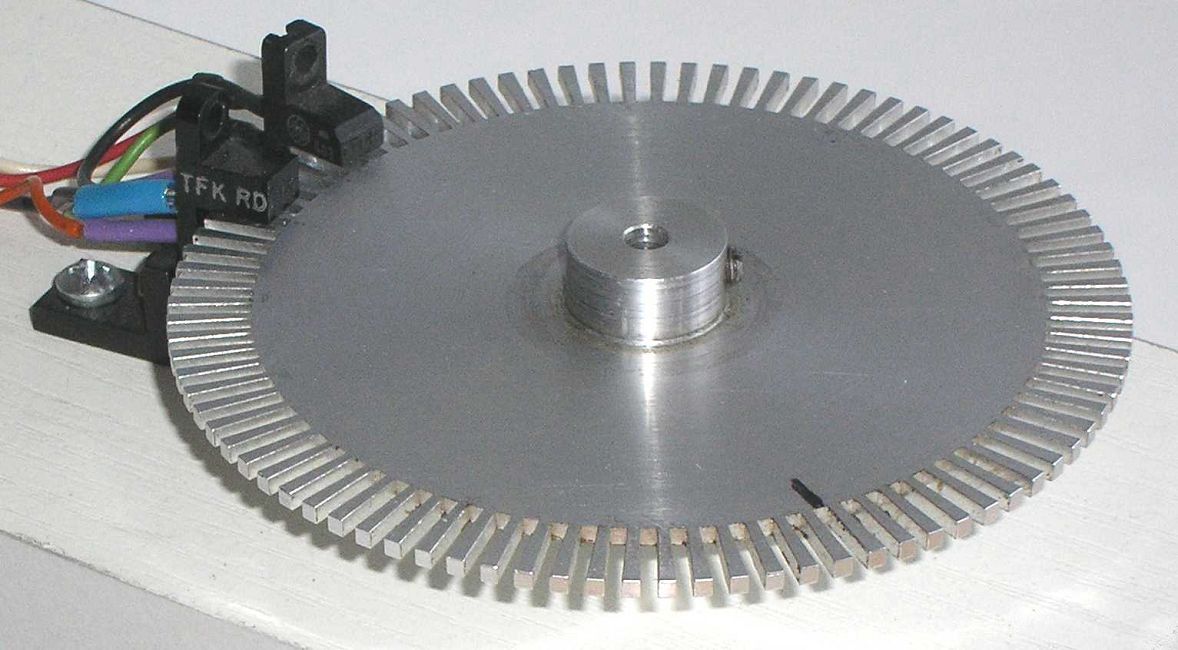
The IE uses a code disk1 and two sensors to produce two square-wave signals: the sensors must be properly placed so that the two waves will be ±90° out-of-phase (hence the term “Quadrature”). Such a device may be built using LEDs, photodiodes, and a code disk to create pulses, or by placing hall effect sensors near a disk made of ferromagnetic materials with alternatively magnetized sectors, and looking at magnetic flux changes as the disk rotates.
The pictures below show a Magnetic and an Optical IE. In the first picture, the two angled ICs placed on the bottom part of the PCB are the Hall Effect Sensors, while in the second picture, the two plastic fixtures with wires house the photodiodes and the LEDs.


Encoding Speed and Direction
If we simply wanted to measure a device’s rotational speed, using an IE would be overkill: a single slit and a photodiode would suffice2, as an impulse would be generated each time the slit passes over the sensor; the speed can be derived from this signal by measuring the frequency of the resulting square wave.
This simplistic approach, however, has a few drawbacks:
- Low granularity - Having a single slit along a circumference means infrequent and potentially inconsistent updates if the “spinny bits” experience sudden changes in velocity or direction, which can only be inferred by looking at how the last n speed measurements differ from each other. This can be remedied by adding more evenly-spaced slits along the circumference of the disk, keeping in mind to divide the frequency of the resulting square wave by the number of slits, to obtain the effective rate of rotation.
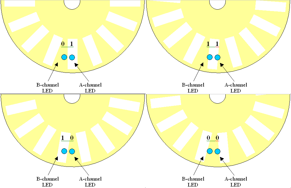
- No directionality - While adding more slits can help with granularity, it won’t be enough if the application needs to determine the direction of rotation, as the pulses generated while moving in either direction will be indistinguishable from each other. IEs solve this problem by adding a second channel which, by construction, is guaranteed to be ±90° out-of-phase from the first one: this property allows us to easily determine the direction of rotation by looking at which channel is leading (i.e. changes first).
The following animations show how rotation is encoded using two sensors and a code disk.


Decoding an IE in software
In this section we refer only to the approach called “Quadrature Reading” or “Quadrature Handling”, which is not based on the level (high/low) of the logic value on each channel at any given time, but rather on the alternation of the square-wave signals’ edges.
While many modern microcontrollers provide hardware units capable of decoding high-frequency Quadrature signals without CPU intervention3, other commonly available devices that only have GPIO ports at their disposal can be used to decode signals generated by an IE in software, as long as the frequency of the square waves isn’t prohibitively high (i.e. the number of ticks per revolution is low enough w.r.t. the clock of the microprocessor) and the electric signal output by the encoder is compatible with the logic levels accepted by the GPIO port.
The CoderBot platform, for example, uses a Raspberry Pi 3 to control a small robot using two independent wheels; speed and direction of each wheel is tracked by a magnetic IE placed on the output shaft of the motor4. The encoder has 16 steps per revolution and the transmission ratio is 1:120, which gives a reasonable amount of positional values per turn. Each encoder’s A and B channels are directly connected to a GPIO input on the Raspberry Pi; the corresponding pins are used as inputs and a callback function is registered when an edge is detected using the libpigpio library.
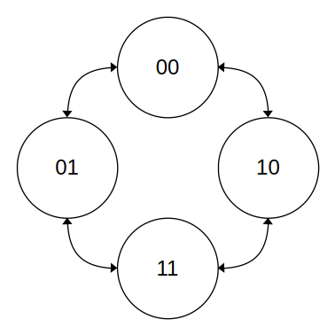
The following diagram illustrates all valid state transitions of a state machine using a 2-bit word to represent the two channels (the MSB represents channel A, in this case).

If channel A leads channel B, the motor is spinning clockwise5, and vice versa. Note how transitions between states 00 and 11, and between 10 and 01 are not valid: this can be easily detected by ensuring that only one bit changes at a time.
libpgpio allows the programmer to assign a callback function, which is also referred to as an Interrupt Service Routine (ISR), to an event (i.e. rising, falling or both edges) on a specific GPIO pin. The ISR must be registered using either gpioSetISRFunc() or gpioSetISRFuncEx(): the only difference between the two is that the latter allows passing a pointer to an arbitrary data structure that may be updated. The following example shows how to register a function as a callback and unregister it when you’re done; keep in mind that the callback’s prototype must be exactly as shown. Specifying a timeout in milliseconds allows the library to abort the execution of an ISR in case it’s taking too long.
#include <stdlib.h>
#include <pigpio.h>

#define BUTTON_PIN 13
#define TIMEOUT_MS 2
#define DEBOUNCE_THRESH_MS 250

typedef struct {
    uint32_t times_pressed;
    uint32_t last_event_ts_us;
} state_t;

void buttonISR(int gpio, int level, uint32_t cur_event_ts_us, void *userdata) {
    state_t* state = (state_t*)userdata;
    {
        // Debounce
        uint32_t prev_event_ts_us = state->last_event_ts_us;
        state->last_event_ts_us = cur_event_ts_us;
        if(cur_event_ts_us <= prev_event_ts_us +
                              (DEBOUNCE_THRESH_MS * 1000))
            return;
    }
    state->times_pressed++;
    return;
}

int main(void) {
    state_t state;
    // Initialize GPIO
    gpioSetMode(BUTTON_PIN, PI_INPUT);
    gpioSetPullUpDown(BUTTON_PIN, PI_PUD_UP);
    // Register ISR
    gpioSetISRFuncEx(BUTTON_PIN, RISING_EDGE, TIMEOUT_MS, buttonISR, (void*)(&state));
    while(state.times_pressed < 10) {
        printf(".");
        sleep(1000);
    }
    // Cancel ISR
    gpioSetISRFuncEx(BUTTON_PIN, RISING_EDGE, 0, NULL);
}
In our case, the ISR should read the value of the channel and update the structure which holds the state of the decoder.
Moreover, since we’re only interested in counting full ticks (i.e. the number of peaks, which is equivalent to the number of rising edges) we only register a tick when the channels show different logic levels by XORing the two channels and incrementing or decrementing the number of ticks, depending on the direction, only if they do.
// Channel A ISR
if(chan_a ^ chan_b) { // Either one of A or B is 1
    direction = FORWARD;
    ticks = ticks + 1;
} else {
    ; // Don't register ticks
}
// Channel B ISR
if(chan_a ^ chan_b) { // Either one of A or B is 1
    direction = BACKWARD;
    ticks = ticks - 1;
} else {
    ; // Don't register ticks
}
When a pulse is received and handled, debouncing must be taken into account: since more than one interrupt can be generated when the square transitions from one logic level to another, due to various factors, the routine must ignore repeated signals from the same channel.
if(last_chan != cur_chan) { // Ensure last interrupt didn't come from current Channel
	// Count ticks, etc.
} else {
	return; // Debounce
}
The libcoderbot library provides an implementation of the decoder as described above6.
-
The code disk, or code wheel, is a wheel that presents slits on the outer circumference. This article and its follow-up expand on the concept of the Incremental Encoder and show how the code wheel works. ↩
-
This method was, for example, used in 5¼” floppy disk drives to measure the speed of rotation of the medium. ↩
-
The STMicroelectronics MCUs, for example, allow the programmer to use a timer as a Quadrature decoder. Source: STM32G4 GPTIM Presentation Notes pp.10-17 ↩
-
Documentation for the DFRobot FIT0450 motor assembly used by the CoderBot can be found here. ↩
-
We may say clockwise, but it really depends on how the sensors are wired, from which side you look at the motor, etc. ↩
-
This may not be the optimal implementation, as the material was written for an university course and the students were expected to come up with their own ideas. ↩
